.
 Applied Membranes | Purchase Online |  Q & A | Technical Articles | Design Information | Search

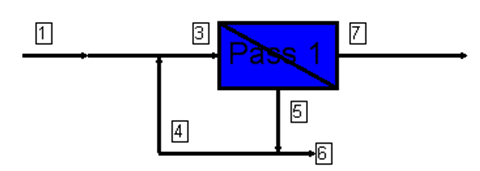
Reverse Osmosis System Design:  Concentrate Recycle Loop


The main purpose of a concentrate recycle loop in a reverse osmosis system is to reduce the amount of concentrate or waste water flowing to the drain. Recycle loops are also used to maintain an optimum flow velocity across the membrane surface and reduce individual membrane recovery.

A recycle loop takes a portion of the concentrate flow which would have otherwise gone to drain and returns it to the feed of the RO pump in a continuous loop. Reducing the concentrate flow to drain achieves a higher system “recovery” percentage. Pump sizing needs to take the additional flow coming from the concentrate recycle loop into consideration.

Careful attention must be paid to the feed water analysis. Concentrating the waste stream to a higher degree can only be done to a certain point before fouling will occur in the membranes. This fouling point will vary with each feed water.

The examples shown below are for the same system operating at 70% recovery, the first example with recycle and the second without:

1. System Design Overview with Recycle Loop

Pass 1

Stream # Flow (GPM) Pressure (psig) TDS (mg/l)
1 = Feed 6.00 0.00 914.82
3 = Pump Flow 9.00 218.37 1650.21
4 = Recycle Flow 3.00 179.92 3087.03
5 = Concentrate Flow 4.80 179.92 3087.03
6 = Final Drain Flow 1.80 179.92 3087.03
7 = Permeate Flow 4.20 -- 5.98
7 = Permeate/1 = Feed % Recovery 70.0

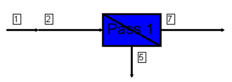
    Design Warnings: -None-

2. System Design Overview Without Recycle

Pass 1

Stream # Flow (GPM) Pressure (psig) TDS (mg/l)
1 = Feed 6.00 0.00 914.82
3 = Pump Flow 6.00 210.50 930.59
5 = Concentrate/Drain Flow 1.8 179.92 3088.81
7 = Permeate Flow 4.20 -- 4.83
7 = Permeate/1 = Feed % Recovery 70.0

Design Warnings:
CAUTION: The concentrate flow rate is less than the recommended minimum flow. Please change your system design to increase concentrate flow rates. (Product: TW30-4040, Limit: 3.00gpm)

WARNING:
Maximum element recovery has been exceeded. Please change your system design to reduce the element recoveries. (Product: TW30-4040, Limit: 25.00%)


Example 1: Without recycle the concentrate to drain would have been 4.8 GPM. A flow of 3 GPM is being returned to the feed in a recycle loop. This reduced the drain flow to 1.8 GPM and made the overall system recovery of 70% possible.

Example 2: 70% recovery without recycle in this system design is too high. System design warnings are shown.

Without a recycle loop the system recovery would need to be reduced to approximately 50% in order to maintain the required minimum concentrate flow and not exceed recommend per element recovery.


Back Home Up Next

 Determining SDI What's Nanofiltration What's Ultrafiltration Membrane Rejection Levels Temperature Correction Pressure Correction Concentrate Recycle Membrane Spectrum Membrane Design 14 Factors for RO Design Water Quality Info Reverse Osmosis Basics Problems with Chloramines and Higher pH Nitrate Removal Ion Exchange Ozone High Purity Water

Applied Membranes Product Selection Links:
[Reverse Osmosis Membranes] [Reverse Osmosis Systems][Home RO Systems][Seawater Desalination Reverse Osmosis Systems] [Media Filters, Carbon Filters, Water Softeners, Etc.] [RO Filters & Housings] [RO Membrane Housings/Pressure Vessels] [Residential RO Components] [Commercial RO Components] [RO Pumps] [Membrane Chemicals] [Ultravioloet (UV) Systems] [Ozone][Water Quality Testers  (SDI)]


All Content on this site is  intended for informational purposes for experienced water treatment professionals only.  Applied Membranes, Inc. does not assume any liability for any damages caused by the misapplication or misinterpretation of any of the information contained on this website.
© Applied Membranes, Inc. 2007